The basic approach in action - a customer's perspective
Dutch shipowner Anthony Veder
Dutch shipowner Anthony Veder is preparing for the ballast water treatment system installation with Goltens’ “basic approach” – shipboard survey combined with the 3-D laser scanning and modeling. Repair and maintenance manager René van Dierendonck explains the reasons behind company’s strategy.
What prompted Anthony Veder to start planning for a ballast water treatment system installation before the ratification of the Ballast Water Management Convention?
“For a large number of vessels in our fleet (mainly our LNG/LPG/LEG carriers of up to 7,500 cubic meters), the size of BWT systems available today is an immense problem in regard to the pipe routing and the space in the engine room.”
Goltens’ 3-D laser scanning and shipboard survey and modeling provides the ultimate approach for us to find out which system – or systems – can be shortlisted. Following that, we will be able to make a decision about which system (or systems) would be the best solution for our fleet. In addition, the 3-D scan will be available later on for the detailed engineering stage.”
Why did Anthony Veder choose to opt for the preliminary design option?
“Like many shipowners, we are not confident that the presently available BWT systems will get the USCG type approval. Choosing an available, suitable and IMO approved system right now could, in the worst case scenario, possibly imply that the investment was worthless – in case the USCG approval does not get through. However, the regulations are not going anyway. Our choice is to start planning smartly in order to be prepared at the time when things get clearer.”
What have you learned from this experience?
“We started with organizing the 3-D laser scanning and modeling and the shipboard survey with Goltens onboard one of our most problematic vessels with respect to available space. The result was that although the space was very tight, it would still be possible to install an available BWT system on board this vessel. We are quite sure that we would not have reached this outcome without having carried out the 3-D scanning and system modeling. This gives us confidence for the rest of the fleet. We will continue with the 3-D scans and the shipboard surveys during the months to come.”
What would you recommend to other shipowners when it comes to planning and executing a BWT system installation?
“I would say, be prepared. There is a lot that can be done in preparation for the BWT system installation without having to make a final decision about which system is finally going to be installed.”
PROJECT FACTS
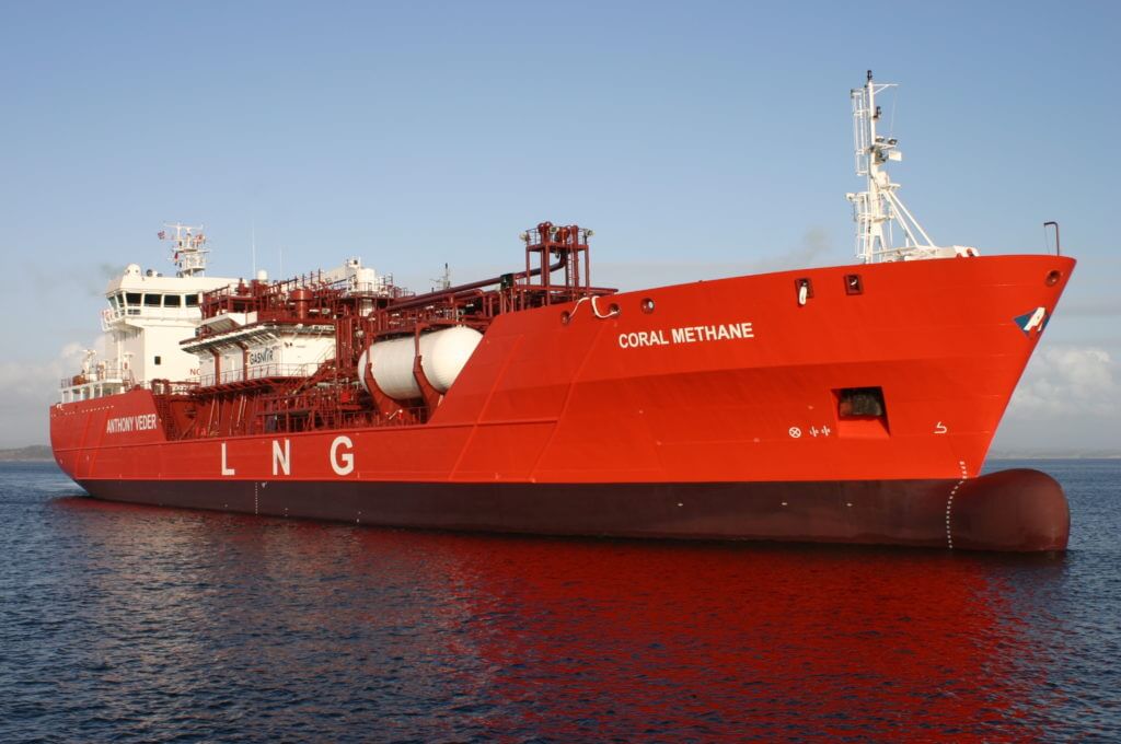
| Name: | Coral Methane |
| Ship type: | LNG tanker |
| Year of build: | 2008 |
| Ballast pump capacity: | 2 x 410 m3/hr |
| Modeled System 1: | Optimarin 835 m3/hr |
| Modeled System 2: | BIO-UV 400 and 800 m3/hr |
GOLTENS GREEN’S WORK ON CORAL METHANE
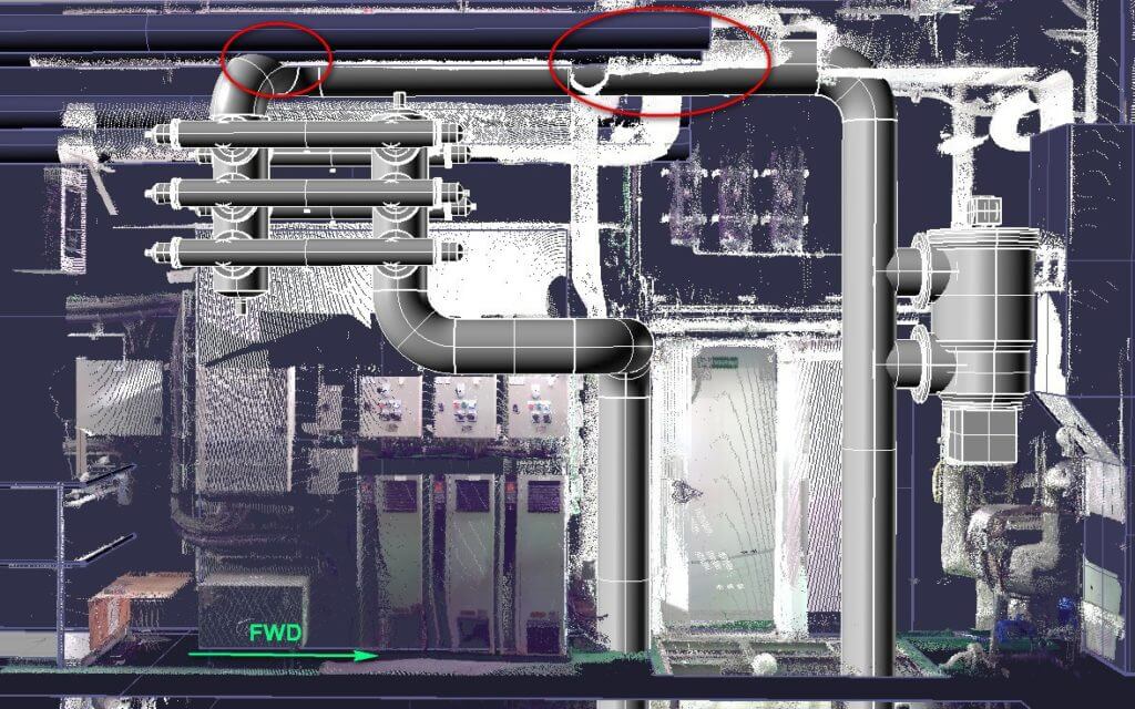
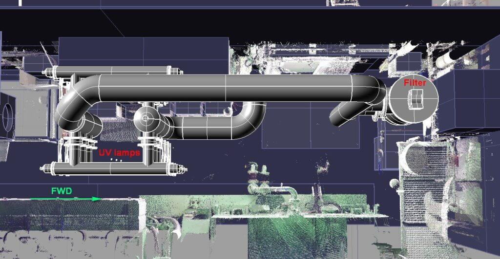
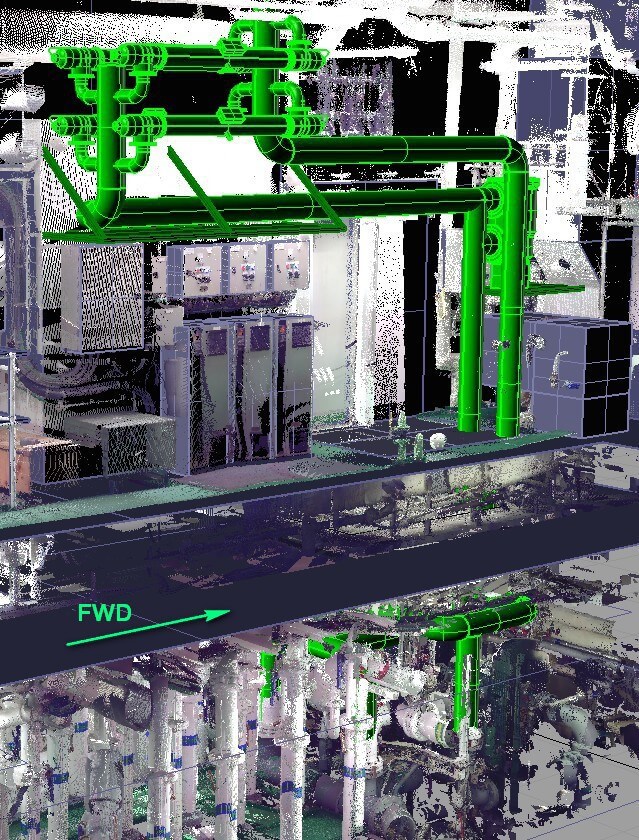
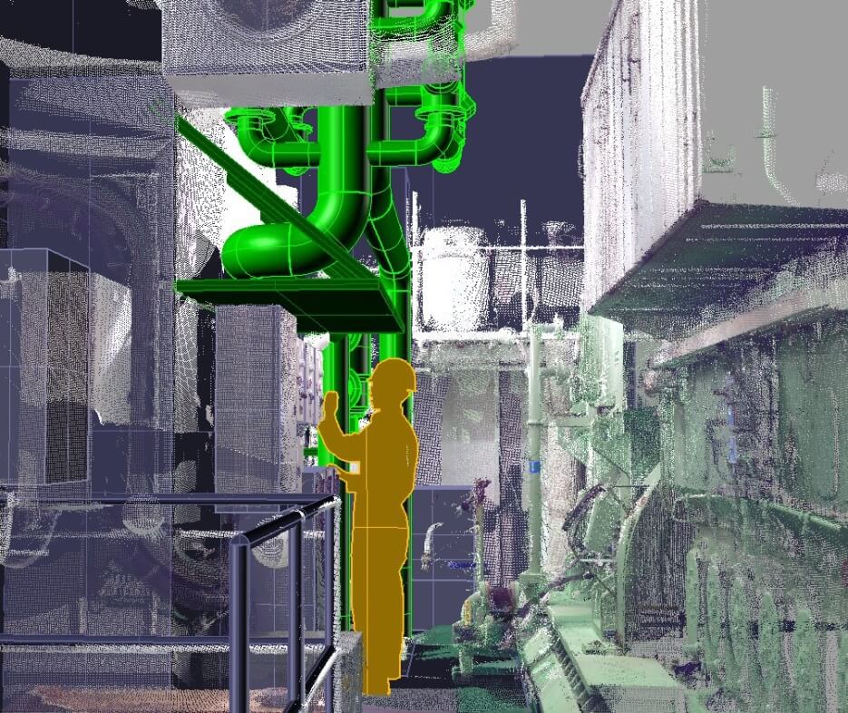
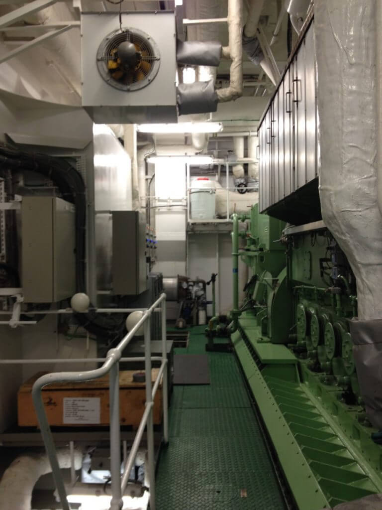
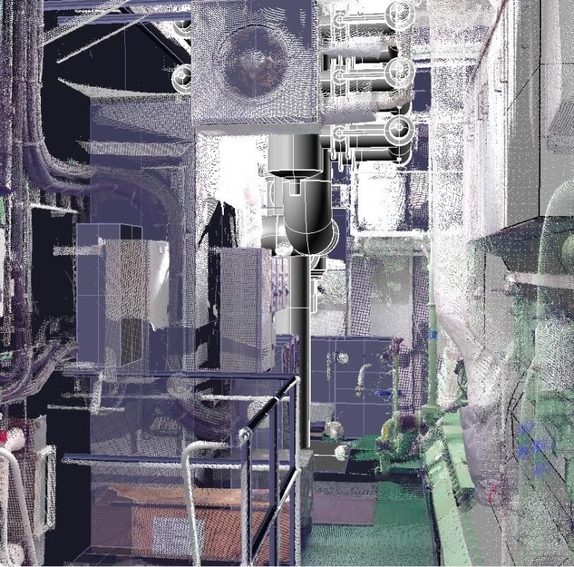
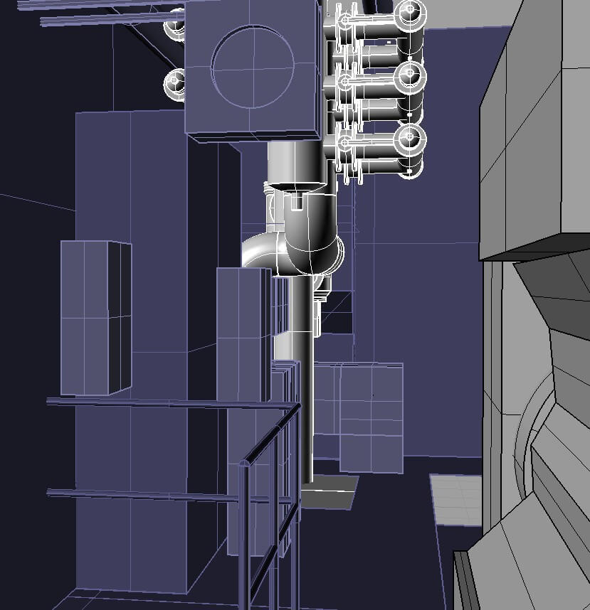
For this ship space was one of the main issues. The ballast pumps are located on the bottom level below the engines leaving no space for a ballast water treatment system. Goltens looked at two of the smallest UV systems on the market and utilized 3D scanning and modeling to determine where the systems could be placed and which system would fit best with the least amount of disruption. The two systems modeled were BIO-UV (a French system) and Optimarin (a Norwegian system).
SCANNING AND MODELING RESULTS
A variety of different locations were tried for both systems identifying piping and structural changes that would be required for both systems.
Goltens determined that both 800 m3/hr systems would not fit without modifying parts of the existing piping. A BIO-UV 400 m3/hr system could be installed with only minor modifications to the vessel if it could function with only one ballast pump operating at a time. As this was not feasible the best 800 m3/hr solution was pursued.
It was determined that the BIO-UV system was simply too large to fit in the available space. As such, the 835 m3/hr Optimarin system using a Filtrex filter was fully modeled. Even with the Optimarin system, numerous piping and equipment modification requirements were identified. These modifications will need to be fully resolved in the detailed design phase.
Download a PDF of this Resource
(Right click and select "Save File As..." or "Save Link As..." to save)
Download Now